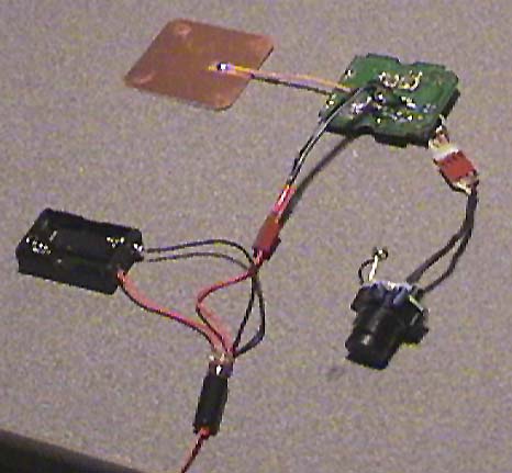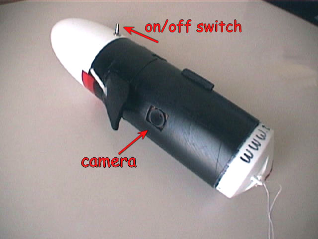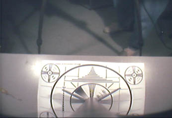
Camera as it comes from X10
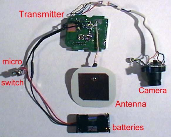
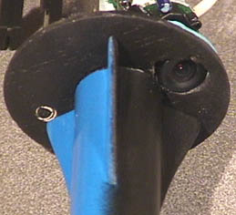
The system removed from the plastic and setup with a power supply
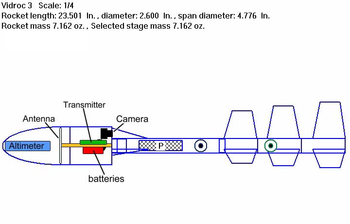
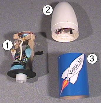
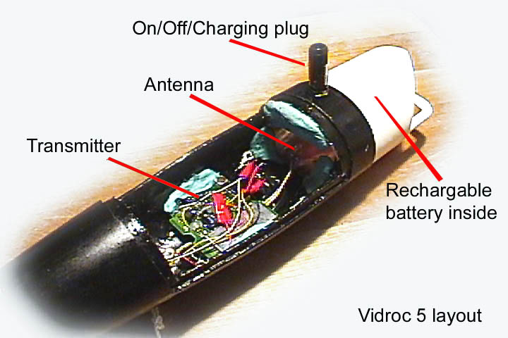
Vidroc Technical information
|
Version |
All my current custom RockSim files in one .ZIP
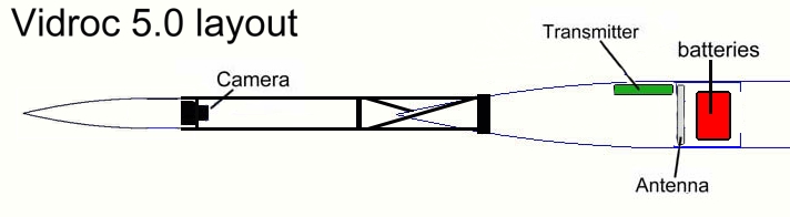
Vidroc basic system was built from an X-10 XCAM, a wireless video camera system you can purchase for under $100.00! The stripped-down system easily fits into the nose cone found on the Estes Silver Comet, Phoenix, large scale V2 or Big Daddy. (Estes part number PNC-80k)
|
Camera as it comes from X10 |
The system removed from the plastic and setup with a power supply |
Receiver
You'll needed a 12 volt power source for the X10 receiver (as the car is often too far away to use.) I picked up a Power Sonic 12
volt PS-1212 rechargeable battery. It's small, light and offers PLENTY of
power for the receiver.
Recording the "flight data"
On the first flight, the broadcast signal from the Vidroc was
recorded to a digital camcorder on the ground. For all later flights I used a Sony Video Walkman to record the signal from the
rocket so I could track the flight with the Camcorder.
By the way, a great source on-line for electronic parts that I use all the time is All Electronics (also, Jameco).
Rocket
The "launch vehicle" for Vidroc 1 through 2.0 was a
D12-powered custom rocket built from the Estes Phoenix kit (that I happened to
have already built.) If you want to duplicate the Vidroc 1.0 style of
camera layout, you might consider using an Estes
Big Daddy.
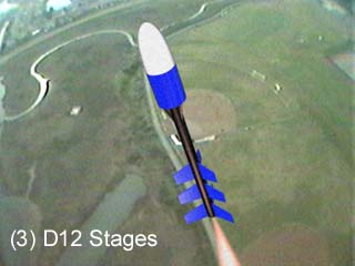
Vidroc 3 flies on a custom built "D" based booster that is lean and mean, the goal being to get the Vidroc to the highest altitude possible to determine where the transmitter signal drops off.
Vidroc 4 (under construction) will be more focused on moving the camera from the nose cone to the body of the rocket and is being built off a North Coast Eliminator (updated to use Aerotech engines).
 |
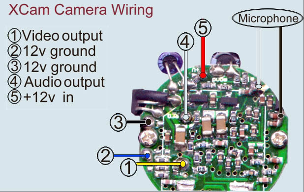
The only real challenge with the XCam system
is that it requires a 12 volt power supply. Tricky thing to come by when weight is critical.
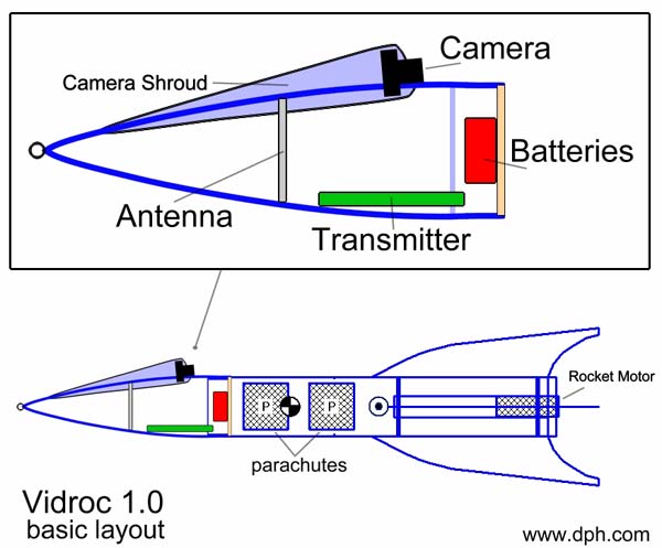
I put together a dual Energizer A23 -12 volt battery system that, in series, delivered 24 volts at peak. This gives about 5 minutes of broadcast time before the voltage drops below 9.5 volts and causes the camera's transmitter to cut out. 5 minutes is more than ample duration for most flights. (Now to find a rechargeable power source. I'll try and outline the process of taking one of these apart in the near future.) The addition of the Vidroc camera added a little less than 2 ounces to the total launch weight. (The nose cone weighs about the same.)
|
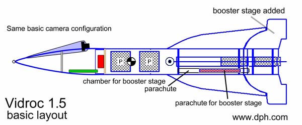 |
Vidroc 1.5 incorporated the following design changes;
|
To take the camera to a higher altitude, I added a lower (1st) stage with its own parachute recovery system that would deploy from a tube in the aft section of the upper (2nd) stage.
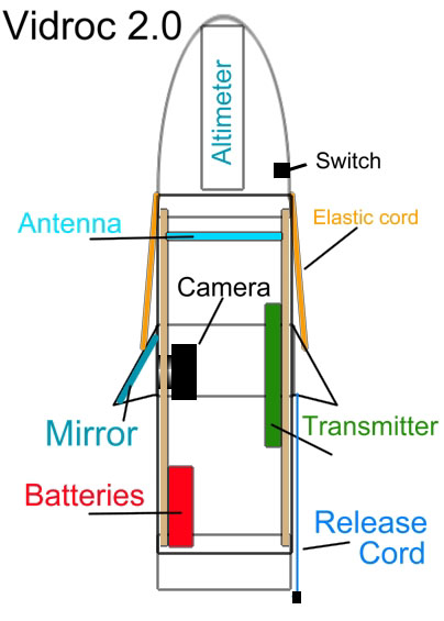 |
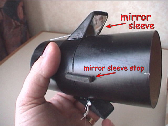
This version incorporates a sliding mirrored hood that allows the camera to look down during launch and retracts to look straight out to the horizon after the parachute has deployed. I used the same launch vehicle that I did for the 1.x systems (shown above) Also, as the most common question I get is "How high did it go?", so I added an Altimeter from Adept Rocketry www.adeptrocektry.com (Here's a link to the ALT05)
|
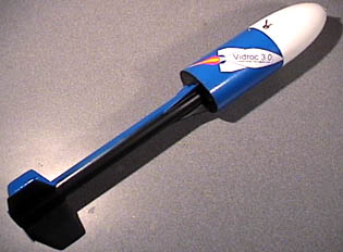
Vidroc 3.0(D)
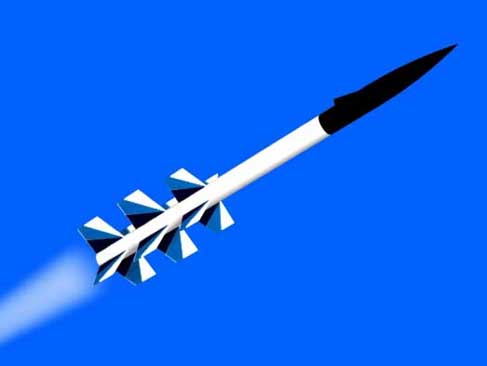
Simulated views of Vidroc 3
Vidroc 3's project goal is two fold. First to build a stable and reliable launch platform and then to fly beyond the signal range of the "stock" X10 camera's transmitter. Note: currently the signal holds strong at 611 feet. I should also mention the first Vidroc's launch platform was never designed for that purpose and after a few crashes I felt it was time to "retire" it. This new system is mean, lean and over stable (at least according to the simulator).
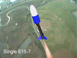
Using Apogee Rockets' RockSim 5.0, I developed a simple 3 stage system. Using D12 motors, RockSim estimates the altitude with a single stage will reach 800', with 2 stages 1400', with 3 stages 2400'. Then I plugged in an Aerotech E15! If RockSim is correct, it will break 2000' with a single engine. I'll most likely develop and fly the multiple stages just because it looks cool on video.
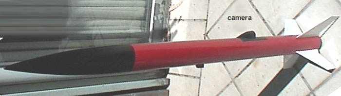
Keeping it simple, Vidroc 3 shares the "access shell" design of Vidroc 2 but instead of a sliding mirror system, the camera easily fits in the offset at the base of the payload section. Not only does this offer a simple construction technique, it keeps the payload section symmetrical, thus reducing any chance it would influence the flight characteristics.
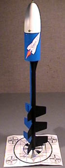 |
I call the rocket component of Vidroc 3, "The Shadow" because of the paint scheme. I liked the blue color but wanted a black matte finish for the camera's field of view. The idea there was to reduce reflected light into the camera, similar to how race car drivers put a matte finish on their car hoods. The resulting paint job makes the booster look like it's casting a shadow on the camera side of the rocket. So there you have it. The Vidroc 3.0 graphic on the side includes the instructions "if found email vidroc@dph.com", just in case the system doesn't return home from one of its voyages.
|
 |
Basic Vidroc 3 components
|
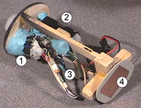 |
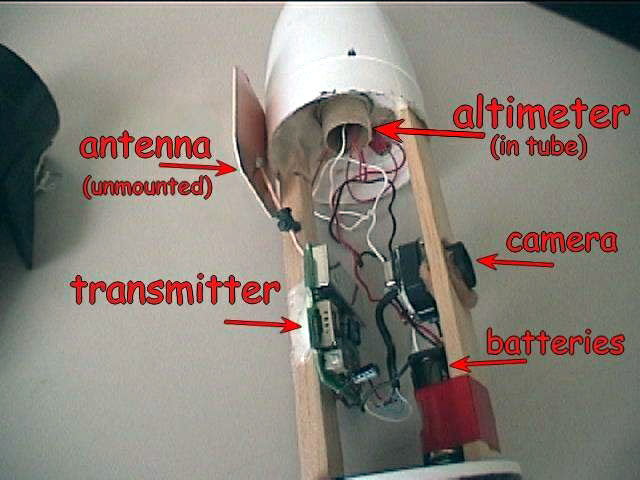
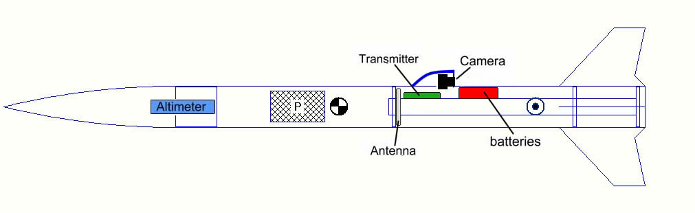
Main electronics section
Note: The blue material is DAP reusable "earthquake" puddy. This makes adjusting the position of the components a lot easier and offers a cushioned mount as well. |
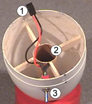 |
Nose cone with Altimeter bay
|
Here's a test image from Vidroc 3.0 |
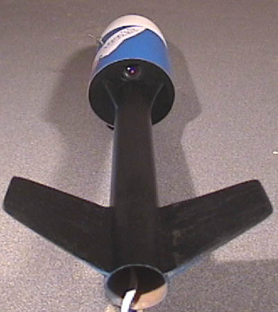
Here's the view of the lens opening from below. Note how in the image on the left the 1/3 matte black paint on The Shadow rocket booster makes it look all black. In the close-up (above) you can see a tiny hole on the left near the blue strut, this is the microphone. FWI: The support struts are to give a better distribution of thrust against the base of the Vidroc 3 payload section. |
Built from a Northcoast Rocketry Eliminator Kit, Vidroc 4 places the camera in the booster section of the rocket. The motivation to mount it there is because the booster, suspended by the parachute from the top, allows the camera to easily look towards the ground when recovering.
The hardest part about this installation is the antenna, as it has to wrap around the ejection charge tube.
In early tests this modified antenna didn't hold up in range, so a 2.4 ghz Dipole antenna was used and that improved things but still wasn't sufficient for the altitude the rocket could reach.
This little bubba stands just under 4' tall.
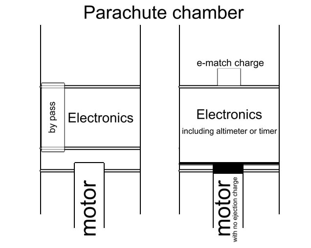
The next step (still untested) in this design will be to build in an ejection charge bypass as show here
.
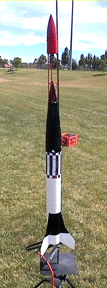
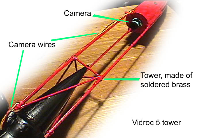
Built from an Aerotech Initiator, the camera rides in the escape tower giving an unique view of the flight. An eyebolt on the side of the nose cone brings it back down horizontal to the ground.
 |
 |
 |
 |
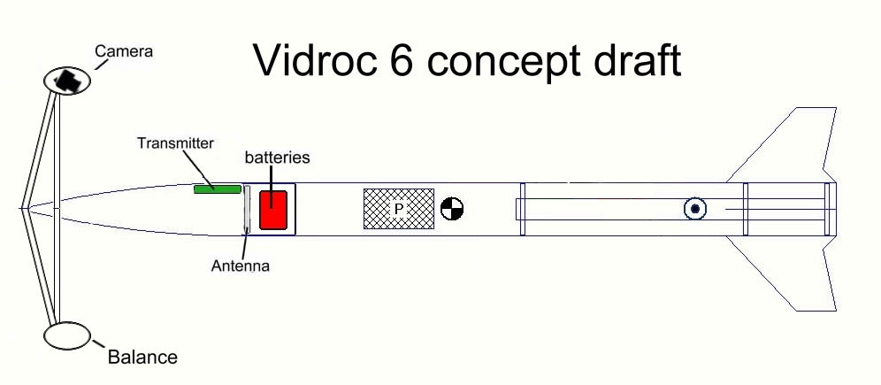
Vidroc 6 - "putting the camera out on a limb"
The idea here is to place the camera out far enough to get a good side view of the rocket as well as seeing the ground pull away.
Preliminary tests are pretty cool, I'll post more as this develops. [This project is currently on hold due to other distractions]
|
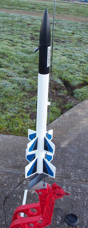
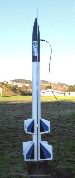
Using Vidroc components this system was built to look like an Estes Cineroc. The booster is a 2 (to 3) stage Omega, the rocket originally designed to loft the Cineroc. Currently the Cineroc 2001 is using an experimental dual antenna system, a 2.4 ghz dipole and custom shaped patch. It looks promising but unfortunately we've not had a clean launch with the new antenna system. The picture on the right shows it ready to go, while on the pad I "warm up" the camera system using an external 12 volt power supply. |
 |